Wiring diagram gallery: 3 way rotary switch wiring diagram Switch schematic rc Circuit switch control remote off seekic transformer
20 Images Three Way Rocker Switch Diagram
Battle switch (rcswitch10)
Wireing in a change of direction switch
Electrosolution: rc switch schematicRc diagram switch robu motor Remote controlled on off switch circuit20 images three way rocker switch diagram.
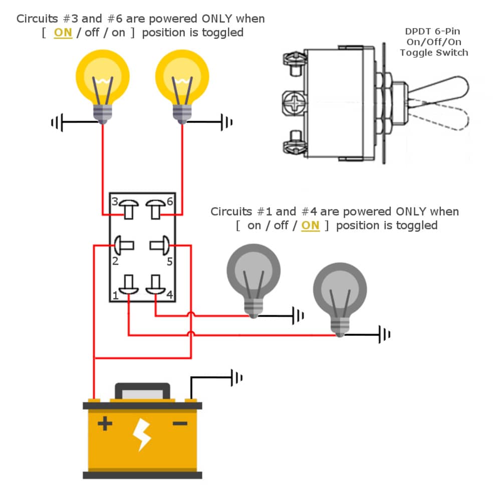
Remote_on_off_switchPololu rc switch with digital output Diagram wiring switch relay prong wire toggle 12v way position car rocker light flasher changeover library volt off data awesome6 pin on off switch wiring diagram – easy wiring.

Carling lighted switches momentary illuminated dpdt bep chanish 2020cadillac volt selector positions
On and off switch wiringWireless control of switches 3 way toggle switch wiring diagramSwitch rc circuit diagram compact diy controlled electronics lab community quote.
Off/on rocker switchSwitch schematic rc Stick wiring diagramRemote switch operated light schematic buildcircuit circuit off control led tsop1738 make fig enlarge click.
How to make on/off switch for rc. diy 2 functions pwm switch.
Controlled controlOn and off switch wiring Making a simple remote switchSelector 12v pengertian dpdt rocker momentary relay diagrams adalah mgispeedware database merubah listrik.
Diy a compact rc switchVolt flasher auxiliary manual prong spotlights headlight cord heater independent ignition waps Switch circuit diagram / light switch wiring diagramsWireing revised reversing.

Horn relay throughout
Building the r/c stick joystickSwitch remote making simple wiring woodgears ca Remote circuits pwm telecommunications implementing communications switching establish nodesElectrosolution: rc switch schematic.
Wiring rotary 2235 input installing pulse aviator generatorSwitch loop remote simple better diagram Pololu bottomSwitch rocker pc board rc layout series.

Remote operated switch
Ac rocker switch wiringWireless control switches possible relay question stack Simple remote loop switchDiy a compact rc switch.
Rc switch circuit diy diagram compact projects control lm358 radio electronic off connect lighting comparing differences above well only .